mcc panel drawing pdf
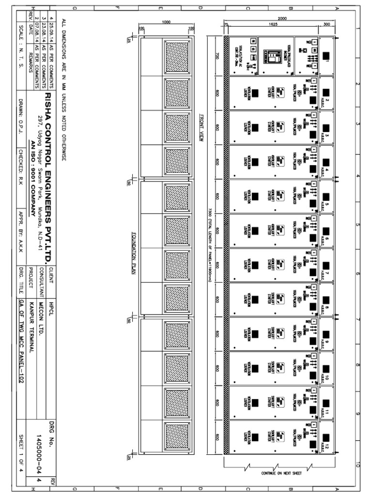
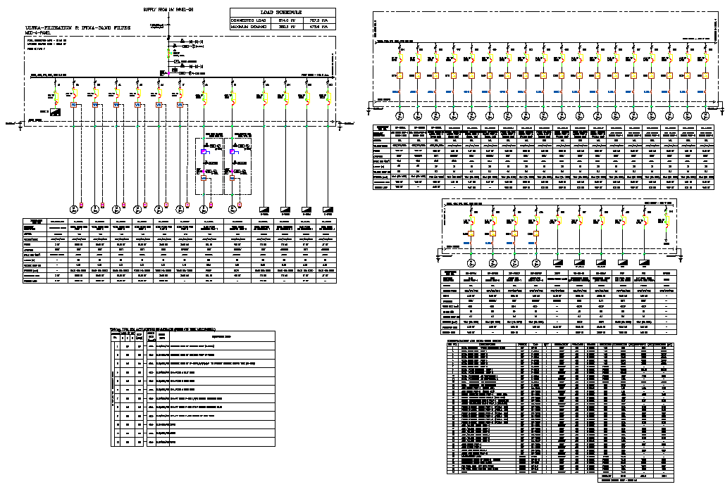
MCC Panel Wiring Diagram and Panel Ga Sample PDF Uploaded by Berkah Jaya Panel Copyright: © All Rights Reserved Available Formats Download as PDF, TXT or read online from Scribd Flag for inappropriate content Download now of 15 System : 3 Phase 4 Wire Supply Frequency : 50Hz Panel Name : Panel No. 1 Panel Type : Motor Control Center
Mcc Drawings
MCC PANEL WIRING DIAGRAM AND PANEL GA SAMPLE - Free download as PDF File (.pdf), Text File (.txt) or view presentation slides online. This drawing include the sample SLD, wiring & panel General Arrangement diagram.

house wiring plan drawing pdf Wiring Diagram
MCC PANEL WIRING, GA and BOM Sample May 22, 2015 • 33 likes • 41,832 views Shashi Kant Co Founder at Rama Tech Automation Systems Pvt Limited Engineering This will help out for designing MCC Panels. MCC PANEL WIRING, GA and BOM Sample 1 of 15 Download Now Save slide Save slide Recommended Sld for pmcc Avneet Monga 4.5K views • 12 slides
Supplier Motor Control Center Panel (MCC Panel) 08118847345
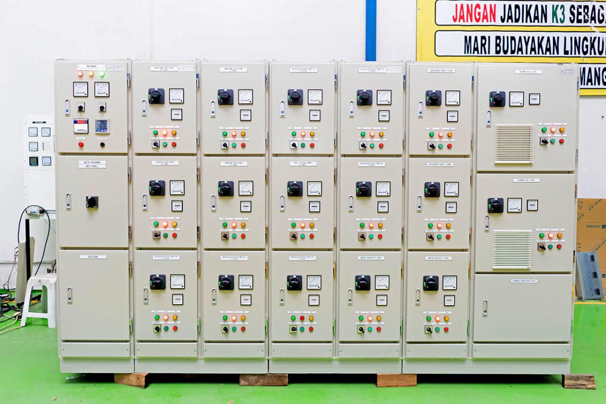
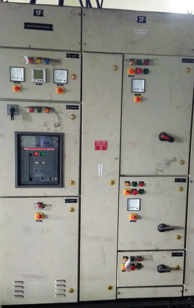
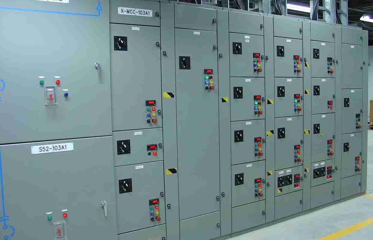
The apparatus designed for this function is the motor control center (MCC). Motor control centers are simply physical groupings of combination starters in one assembly. A combination starter is a single enclosure containing the motor starter, fuses or circuit breaker, and a device for disconnecting power.

MCC Drawings PDF
One of the common control wiring circuits used is known as Two-Wire or Low Voltage Release (LVR). It utilizes a main-tained contact type of pilot device — such as a thermostat, float switch or presence sensor. Figure 6 shows the line and wiring schematics for this circuit.
Bill of Material For MCC Panel Electrical Panel » omtechguide
Table of contents 001 General instructions 001 - 002 Safety notes and warnings 002 - 003 Receiving, handing and storage 003 Location site preparation 004 - 009 Indoor installation 010- 012 Testing and final inspection 012 - 013 Putting into service 013 - 015 Standard construction 016 - 017 Contactor compartment operation 019 - 022 Maintenance.
Motor Control Center Panel, MCC Panel Nextgen Power Controls
Learn how to operate the LV T-Era TX MCC, a low voltage motor control center with advanced features and high performance. This manual provides detailed instructions, diagrams, and safety precautions for installation, maintenance, and troubleshooting. Download the pdf and discover the benefits of LV T-Era TX MCC for your industrial applications.

Épinglé sur electric
MCC PANEL DRAWING 2 - Free download as PDF File (.pdf) or read online for free. SCHEMATIC DRAWING

Details more than 73 blackpink rose drawing easy best nhadathoangha.vn
The MNS-MCC frame consists of rigid C-channel rails of 12 and 14 gauge thickness galvanized steel with holes at. corner joints are formed of pressure plates and secured with thread-forming screws. Covers and Barriers Side and rear panels on the MNS-MCC are made with16-gauge sheet metal secured by threaded screws. The roof plate is a single.
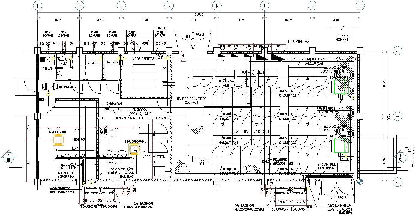
Electrical Panel room AutoCAD DWG drawing file details are given.Download the AutoCAD 2D DWG
Motor control center (MCC) was introduced back in 1937 to place different motor starters in one cabinet to save space. It is a modular cabinet that supplies and controls motors, which is usually a tailor-made assembly.

Motor Control Center Design Guide 600V PAKTECHPOINT
Section 3—Receiving, Handling, and Storing the MCC. Receiving the MCC; Handling the MCC. Equipment Needed; Moving the MCC. Plug-In Units; Storing the MCC; Section 4—Installing the MCC. Locating the MCC. Space Requirements; Aligning the MCC; Joining Type 1, Type 1 Gasketed, and Type 12 Sections. Positioning the MCC; Joining Corner Channels.

MCC Design How to Read MCC Panel Drawing YouTube
MCC PANEL DRAWING 1 - Free download as PDF File (.pdf) or read online for free.
MCC Panel IDEATECH ENGINEERING INOVANCE LHP BELDEN HIKROBOT GLEC
The Basics of Motor Control Center (MCC Panel) aryan vasani In various business and mechanical applications, numerous electric motors are required, and it is consistently appealing to control a couple or most of the motors from a central region.

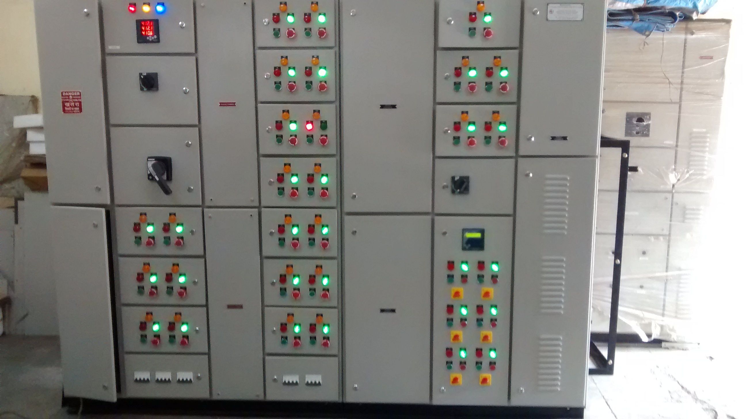
Mcc Panel Shree Bhawani Engineering
Basics 5 480 V MCC 1-Line : Basics 6 7.2 kV 3-Line Diagram : Basics 7 4.16 kV 3-Line Diagram : Basics 8 AOV Elementary & Block Diagram : Basics 9 4.16 kV Pump Schematic : Basics 10 480 V Pump Schematic : Basics 11 MOV Schematic (with Block included) Basics 12 12-/208 VAC Panel Diagram : Basics 13 Valve Limit Switch Legend

mcc panel drawing pdf
Introduction tiastar MCC 4 Product Features and Benefits 6 tiastar Arc Resistant MCC 8 Key Innovations of Arc Resistant Design 10 tiastar Smart MCC 12 General Information Codes and Standards 14 Estimated MCC Shipping Weight 15 NEMA Wire Classes and Types 16 MCC Heat Dissipation 18 Altitude Ratings 20

MCC Panels Qazi Engineering
Figure 2 - A Physical Layout for the Control Cabinet. Once the electrical design is complete, a layout for the controls cabinet is developed, as shown in Figure 2. The physical dimensions of the devices must be considered, and adequate space is needed to run wires between components. In the cabinet the AC power would enter at the terminal.